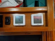
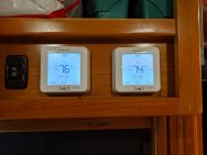
If you’re like me, you tend to sleep with the temperature quite a bit colder than your daytime setting. My specific setpoints are:
76 °F for the day time, and 68 °F at night for the summer.
71 °F for the day time, and 64 °F at night for the winter.
While it’s a little thing, it’s becomes tedious to do these settings changes every evening / morning, especially knowing there are so many programmable and/or Smart thermostats on the market for the household climate control systems.
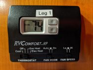
However, the RV world is woefully lacking of any type of programmability on the thermostats. Worse yet, RV AC/Heatpumps have some things stacked against them when looking for aftermarket kit:
- RV AC/Heatpumps made the weird choice to use 12 Vdc control panels (instead of 24vac) — as if you could run them without 120 Vac power?
- RVs can often have more ‘heat’ options than our sticks & bricks brethren.
- RVs also tend to have two speed fans in our AC/Heatpumps
This all combines to make replacing an RV thermostat with anything other than the OEM unit a daunting task.
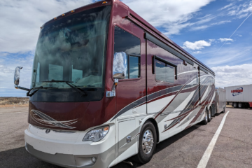
Being the inventor of CoachProxy, and knowing Tiffin opted for RV-C enabled thermostats on newer coaches… I had initially thought about retrofitting those new thermostats into my coach. Alas, that is not as easy as it sounds. Turns out, there is a LOT of changes in the wiring and Spyder Controls system that goes along with those RV-C enabled climate controls. So, this was off the table.
I also considered building my own climate control system based on an Arduino + some relays… and I bought the stuff to do a test unit, but there’s never enough time and I never got that elusive “round tuit”.
Recently, I started looking at integrating some Z-wave items into the coach ( Aeotec Home Energy Monitor, Multi-sensors, remotes ) and thought, there has to be a Z-wave option out there that will work. The big caveat is that they must be able to run on battery alone ( No 24vac / Common wire requirement ), OR run on 12vdc natively. One thermostat actually did run on 12vdc and another RV’er -Adventurous Way- has a great post on their installation! However, it no longer seems to be made and trying to get one is like trying to get unobtainium. So, I kept searching and found that Honeywell makes a unit that is able to run on battery power alone!
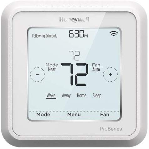
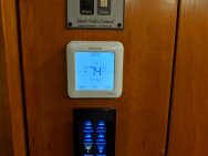
I present to you, the cleverly named Honeywell TH6320ZW2003 Z-Wave T6 Pro Programmable Thermostat.
Note that you’ll need a couple more items besides the thermostat. At least, in our situation because:
- Our roof mounted AC’s are actually Heat Pumps
- We also have the AquaHot system which can supply heat via fan blown radiators
- We have remote temperature sensor — separate from our thermostats
- Coleman Mach systems use a 100 kΩ thermistor — not the standard 10 kΩ or 20 kΩ versions that most household units use.
Supplies:
- Honeywell TH6320ZW2003 Z-Wave T6 Pro Programmable Thermostat
- Remote temperature sensor: 10kΩ B3540 Thermistor
- 12v Automotive Relay
- Heat Shrink
- Soldering iron, supplies, skills
Why the relay?
When switching to heat mode, regular sticks & bricks heat pumps use 1 wire to run the compressor, 1 wire to run the blower, and 1 wire to toggle a ‘reversing valve’: this switches the flow of refrigerant inside the heat pump to make the heat pump ‘heat’ instead of ‘cool’.
RV Heat Pumps are slightly different. They use 1 wire for the compressor in cool mode, 1 wire for the low blower (when in cool mode) and 1 wire for high speed on the blower (again, when in cool mode). A ‘heat’ wire is used by itself to call for ‘heat’ from the heat pump. This ‘heat’ wire handles compressor, reversing valve and blower all at the same time. When calling for ‘heat’ via this ‘heat’ wire, the heat pump will ignore the blower wire signal (low or high, doesn’t matter).
The relay is used to convert the ‘compressor+reversing valve’ signal to just a ‘heat’ wire signal for the RV heat pump. If your roof mounted AC is *not* a heat pump, you can likely omit this relay, but you’ll need to determine that for yourself since different units and different manufacturers may behave differently.
Operation of our setup:
- During cooling, the thermostat will automatically kick the fan speed to high if the temperature is too far above the set point.
- When set to ‘Heat’ mode, the thermostat will use the heat pump (with fall back to AquaHot heat if the room temperature is too far below the set point).
- If we want to use AquaHot as the primary source, we set the thermostat to ‘Emergency Heat’ mode. This locks out the Heat Pump and uses the AquaHot heat only.
UPDATE!
David from Outside Our Bubble stopped by. So, we decided to do a live stream installing one of these thermostats in his coach! Feel free to watch the recorded session, or just continue below with the text/photo version of an installation.
Installation:
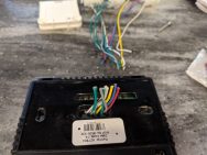
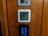
- Snap off the thermostat cover and remove the two screws securing it to the wall.
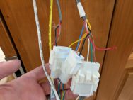
- Disconnect the quick connector plugs.
- Cut the wires off the thermostat and strip 1/4″ of the insulation from the plug side wires.
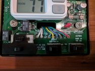
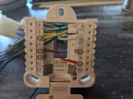
- Insert the stripped ends of the wires into the wiring base / new thermostat as shown.
- Yellow – Y
- Green – Y2
- Gray – G
- White/Black stripe – O/B
- White – W2
- Red – R
- Green/White stripe (2 wires) – The ‘S’ Terminals, one in each.
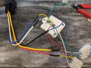
- Cut the Yellow and White w/ Black stripe wires at their mid point.
- Wire in the 12v Automotive Relay to the newly cut wires as shown:
- Relay 30 ( Common ) Blue Wire –> Thermostat side Yellow Wire
- Relay 87a ( Normally Closed ) Red Wire –> Connector side Yellow Wire
- Relay 87 ( Normally Open ) Yellow –> Connector side White w/ Black stripe
- Relay 85 ( Coil ) Black –> Connector side Blue (Ground Wire)
- Relay 86 ( Coil ) White –> Thermostat side White w/ Black stripe
NOTE: The relay socket wire colors may be different — Use the relay pin numbers to confirm.
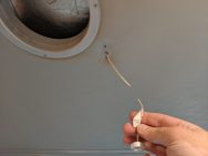
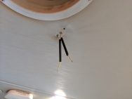
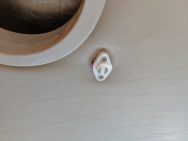
- Unscrew the old remote temperature sensor and cut the wire.
- Separate the two wires ceiling side wires
- Strip about 1/4″ of the insulation and slide a good length of heat shrink over the ceiling side wires.
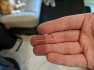
- Bend the new 10kΩ B3540 thermistor leads as shown.
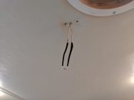
- Solder the new 10kΩ B3450 thermistor to the ceiling side wires — which wire goes where doesn’t matter.
- Slide the heat shrink down over the thermistor, leaving about 1/8″ of the long side of the thermistor wires exposed and heat the shrink tubing to shrink it in place.
- Push the thermistor wires back up into the ceiling and bend the remainder out to the side of the outline from the old room temperature sensor as shown.
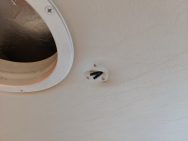
- Slide the cut portion of the old room temperature sensor through the ceiling hole and screw it back into place — ensure the exposed thermistor wire is left out from under the old temperature sensor.
- Bend the thermistor down alongside the old thermistor.
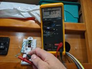
- Test the resistance of the Green with White stripe wires at the thermostat connector and ensure they’re in the 7 kΩ to 12 kΩ range (depending on room temperature).
- Plug in the newly wired thermostat base and screw it to the wall.
- Put the 3x AA batteries in the thermostat and begin the programming — do not plug it onto the wall plate until programmed. Note that each setting has a numeric ID at the top of the thermostat. I’ve included them below for your convenience. Here are the settings we used:
Expand for full settings...- #120 – Schedule Type: none (When using Z-wave, the schedule does nothing anyway)
- #130 – Outdoor Temp Sensor: No
- #200 – System Type: Heat Pump
- #205 – Equipment Type: Air-to-Air
- #218 – O/B On – Heat
- #220 – Compressor Stages: 2
- #221 – Aux/E Stages: 1
- #253 – Both Aux/E Control
- #255 – Aux Heat Type: Gas/Oil
- #260 – Fossil Kit Control: Thermostat
- #300 – Auto Changeover: Off — I’ll script this via Z-wave controls
- #305 – High Cool Stage Finish: No
- #306 – High Heat Stage Finish: No
- #340 – Aux Heat Droop: 15
- #350 – Up Stage Timer Aux Heat: Off
- #355 – Balance Point: Off
- #356 – Aux Heat Lock out: Off
- #365 – Compressor 1 CPH: 3
- #366 – Compressor 2 CPH: 3
- #375 – Aux Heat CPH: 5
- #387 – Compressor Protection: 5 minutes
- #390 – Ext Fan Run Time in Cool: Off
- #391 – Ext Fan Run Time in Heat: Off
- #430 – Min Cool Temperature: 50
- #431 – Max Heat Temperature: 90
- #500 – Indoor Sensor: Yes
- #515 – Sensor Type: 10k
- #520 – Temperature Control: Wired
- The rest are up to you…
[collapse] - Once programmed, click ‘Finish’
- Set the Date/Time
- You’ll likely get an immediate error about the wired temperature sensor, this is expected — it’s not connected yet.
- Press and hold the ‘Menu’ button to get back to the setup screens
- Use the left/right arrows to get to ‘System Test’
- Snap the thermostat onto the wall plate
- Press ‘Select’ and cycle through your systems heat/cool modes to confirm everything works as expected
NOTE: Going from Heat to Cool on the Heat pump too quickly can damage the compressor — Allow at least 5 minutes between testing each mode. - Once all seems right, exit the System Test menus and set your mode / temperature and ENJOY!
Future plans…
The main thing I’d like to change is to have the thermostat powered from a DC converter, not batteries. There are adjustable DC-DC converters on Amazon, but seems when the potentiometer on these ‘adjustable’ units fails, they fail in a way to cause the voltage to go high, thus likely damaging your sensitive electronics. I may test a standard ‘5v’ supply to see if the extra 0.5 volts is OK and just run them from that 5v converter.
Documentation Links
Airxcel Service Manual for Mach8 Heat Pumps
On page 8, under ‘VII Low Voltage Wiring’, there is an explanation of what each color wire performs.
Airxcel Thermostat Installation, Operation and Application Guide
On page 6, Figure 1: A complete pin-out description for the original thermostat

14 Comments
Jim Beletti · 2019-09-29 at 18:17
Love it Michael – can’t wait to add these to my coach in a couple weeks.
Matt Knight · 2019-11-12 at 09:08
Hey – Matt here from Adventruous Way! As you said in your post, obtaining the Radio Thermostat that we used isn’t easy, so love that you’ve found an alternative!
How’s it working out for you so far?
Also, as for powering it from DC, maybe a 5V voltage regulator combined with a voltage divider would be a safe and reliable way of getting 4.5V exactly, although my guess is that it’d be fine with 5V.
Michael · 2019-11-12 at 09:27
Hi Matt!
Thanks for stopping by. The Honeywell thermostat is working very well. I bought some adjustable DC-DC converters so I can tweak the output, but I suspect like you, that 5v would be fine (haven’t installed them yet…) Unfortunately, even if I replace the batteries with the DC-DC converter, the thermostat still thinks it’s on battery so it doesn’t enable the Z-wave repeater function to conserve power.
I would love to be able to supply it off of an AC transformer via the R+C wires so the thermostats would enable the Z-wave repeater function. I may look into creating an adapter board to facilitate this and if I do, I’ll definitely post about it. 🙂
Thanks again for your trail blazing on this front!
Michael
Kevin LaTour · 2019-11-23 at 12:57
Any chance you will be working on a mod to use the NEST Thermostats ? Also is the coach proxy mod no longer available ? if not what happened ? thanks
Michael · 2019-11-23 at 17:21
Hi Kevin,
The main requirement for the RV T-stat mod is that the T-stat must be able to run off battery power full time. Several smart thermostats ( esp those with WiFi built in ) require the C wire and 24vac from a furnace based transformer. Since RV air handling systems all run off of 12vdc, those smart T-stats requiring 24vac for normal operation are not an option ( at least, not without a conversion board / relays, etc — a lot more work ). From a technical perspective, the modification is not complex, but it does require a lot more components and is beyond the scope of most RVers.
CoachProxy is no longer being sold as a product. You can however build your own as the software behind CoachProxy is now open source. Check out the CoachProxy.com site as it has all the details.
Ellis Clark · 2019-11-27 at 09:00
I actually did a similar replacement of the Coleman Mach thermostat (2 of them). I was going back and forth with the Nest and the ecobee 3. I chose the ecobee 3 because it had the remote sensors that help you better control the area inside of the Motorcoach.
I saw you and Dave from OOB mentioned that was not possible because of the voltage but what I did was to use a 120vac/24vac transformer and some relays to get the feeds they need. the wiring was the challenge. I had to go with a 2 stage cooling and 2 stage heating wiring.
My a/c units are the Coleman Mach 3 and they do not have heat pumps. I followed ideas from the 2 links below. The first one shows how to use the relays with the 24 v transformer; the second one shows how to do the wiring.
https://www.youtube.com/watch?v=VQjtQMRPIjc
https://janeandjohn.org/pages/Ecobee2.html
Michael · 2019-11-27 at 09:07
Hi Ellis,
Thanks for bringing this up. I had a thought of going this route as well, but as you pointed out, there is a much higher wiring challenge. Not a big issue for me specifically, but most RV’ers would not be comfortable with that level of modification. I should have mentioned this on the live stream for sure. Glad your units are working well for you and thanks for the links!
Thanks!
Michael
Larry · 2019-11-27 at 13:52
Michael, I watched the video with David. Thanks for doing it live. Our Tiffin Phaeton has a single RV Comfort thermostat controlling 3 zones. I select a zone first then it works like the ones you replaced in the video. My assumption would be that I would need 3 of the Honeywell thermostats, relays, thermistors, etc., and some physical alterations at the location to mount the 2 additional thermostats. My question is if you have seen what is “behind the wall” on a system like mine. I assume that there is some additional electronics that must be considered. Thanks! Larry
Michael · 2019-11-27 at 23:09
Hi Larry,
While I’ve seen the type of 3 zone thermostats you have, I’ve not done much with them. So, while I don’t think a simple thermostat swap is possible, I’m not 100% certain since I’ve not worked with those systems before. Wish I had a better answer for you.
All the best,
Michael
John Walker · 2019-11-28 at 05:47
Mike
I watched your video with David and would love to do what you guys did but as David knows I am not a geek as you guys. I can do the wiring but I won’t understand all the geek stuff. I have a 2014 Tiffin Red 33AA with heat pumps, no agua hot so would my install be exactly the same? Also, why couldn’t you have used wire connectors instead of soldering them together? Thanks for the video. Did David show you my wife’s Bowl Cozies?
Michael · 2019-11-28 at 07:01
Hi John,
Assuming you do have some source of fuel fired heat ( propane furnace? ), the install wiring should be practically identical. Since you have a heat pump, you would still need the relay, however if you don’t have remote temperature sensing, you would not require the thermistor.
I soldered the connections because it’s my default for joining wires and with RV walls sometimes being thin, the crimp butt splice connectors can become a bit bulky. However, if you have room behind your T-stat for them, the crimp connectors would work just fine. You could even use twist on wire-nuts if you were not wanting to crimp… as long as the connection is solid.
I’ve not seen the Bowl Cozies! I’ll have to ask David to show me 😀 Hope all this helps and best of luck!
Michael
Jeff Dickinson · 2019-12-15 at 08:24
I just changed my 3 thermostats in our 2014 45LP, my wife accuses me of trying to keep up with David and Brenda upgrading our bus. She’s not wrong! I had a heck of a time with the front unit trying to get the relay into the wall next to the relay. I couldn’t figure out how David got his relay on top of the refrigerator. I realized the wall has some “flex” so i trimmed off all of the excess material off the relay and connector and “gently” pulled on the wall and the relay fell behind the wall. I’m going with it’s snug between the wall and the refrigerator and the worse case would be the fridge will have a small impression from the tension over time a dent we will never see. You said in the post you were going to program the units a z wave controller. Is this a home built via a raspberry pi or a off the shelf unit? The only automated thing on our bus is the LED lights I installed from Govee and they work with our Alexa stuff. We also added a water control valve to control the black tank flush system. We can now open and close our tanks with the drain master system and open the flush with a 30 dollar wifi control valve. Sure is nice to clean the tank and not have to go out in the 30 degree rain last week. Please let me know how to plan to communicate with the thermostats.
Michael · 2019-12-15 at 14:58
Hi Jeff,
The thermostats should work fine with most Z-wave enabled home automation hubs. David and I are currently using HomeSeer, but it is not the most friendly to get working with the various voice assistants. I’m going to be playing with HomeAssistant soon, but it is currently more geared toward programmer types from what I can tell. HomeSeer works after you get through the steep learning curve, and they’re having several things on sale during this time of year.. but to do something that seems simple ( like… synchronizing all 3 thermostats to the same temp / mode, and having that sync’d setting work via voice assistants.. ) takes dropping some VisualBasic code into the scripts folder and creating virtual devices that trigger events, etc… Not for the faint of heart.
Regarding the relay on David’s “front” thermostat — I used some stranded network cable to extend the wires of the relay socket, then fished that network wire down from above the fridge ( we removed the top trim board, and used a multi-tool to cut away part of the board behind that.. this allowed room for the relay itself on top of the fridge ). I then soldered the network cable into the T-stat harness just as the relay would have been.
Nice mod on the tank flush control! We’ve been talking about doing something similar… David found a Wi-Fi valve (probably similar to what you have), and I have a +12vdc solenoid controlled valve.. but neither of us have taken the time to install them.
Best of luck w/ the Z-wave!
Michael
Jeff Dickinson · 2019-12-15 at 15:10
Michael thanks for the details on the relay. The water shut off valve took about 15 minutes to install in my system. And the 12v power was already there with the dump valves.
Smart Thermostat – Follow up – TurtleHerding · 2019-11-26 at 19:00
[…] classic Outside Our Bubble style, we opted to perform the installation LIVE! I’ve updated the original posting with the video, and I’m including it here for your […]
Comments are closed.