That is not a typo… our RV is now powered by TESLA! Well, Tesla battery modules that is! Oh, and the Sun! Yes, the Sun, too!
WARNING — This post is full of technical content. Here’s the TLDR;
Our original House batteries only powered part of our coach via the inverter, and could only power the coach in a boondock situation for about 4 to 6 hours. After that, the battery voltages were below 11.8vdc and we’d have to start the Generator.
Our new Tesla batteries can power ALL of the coach, not every load in parallel, but 2 of 3 ACs can be running at the same time! Given the same loads that would only last 4 to 6 hours on the old batteries, we can now last indefinitely on the batteries / solar combo!
Check the bottom of the post for loads of photos!
I’m not the first!
Nope… I’m not the first to have braved this path. I may be the first with this exact combination, but ultimately I stand on the shoulders of giants. Here’s a link to a YouTube playlist of videos I used along the way.
YouTube Playlist: LiPo and Solar Installs
And a special thanks to Tom of Mortons on the Move. It was his videos & posts that gave me the final push to get this project in motion!
Mildly Technical Stuff:
| Old System | New System | |
|---|---|---|
| Batteries: | 6v US2000 FLA | 24v Tesla LiPo |
| Maximum Capacity: | 216 aH | 200 aH |
| Nominal Voltage: | 6.5 Vdc | 22.5 Vdc |
| Configuration: | 2s 3p | 4p |
| Pack Maximum Capacity: | 8.4 kWh | 18.0 kWh |
| Pack Usable Capacity: | 4.2 kWh | 14.4 kWh |
| Inverting Capacity: | 2.8 kW | 8.0 kW |
| Solar Capacity: | 145 W | 1800 W |
- Q1: Why is Usable Capacity 1/2 of Maximum Capacity for the Flooded Lead Acid batteries?
- Discharging Flooded Lead Acid batteries below 50% causes permanent damage and a reduction of future capacity and charge cycles.
- Q2: Are there any limitations or downsides to the LiPo pack?
- Yes, a few things that must be kept in mind..
- The packs *MUST NOT* be charged while below freezing temperature.
- This will destroy the pack. They can be discharged below freezing, but not charged.
- The packs *MUST NOT* be charged above their rated Maximum Voltage
- Doing so causes permanent damage and may result in a fire!
- The packs *MUST NOT* be discharged below their rated Minimum Voltage
- Doing so causes permanent damage.
- The packs *MUST NOT* be charged while below freezing temperature.
- Q3: How long did this take to install?
- The installation took place in a three main phases:
- Planning!
I spent almost 2 full months researching every aspect of the system. Again, I have an extensive electronics and electricity background, but there was much to learn and many items that needed to go into the system. Each of those items had multiple possible options with varying costs, capabilities, and limitations.Even with all that research, I messed up on the DC-to-DC converter decision. The first one I bought was an Eaton 21100C00. It was an industrial unit rated for 100 Amps of 13.5 vdc output with an input range much wider than my maximum range of 18.0 to 25.2 volts. It was expensive ( $600 ), but I thought with the specs and industrial design, it’d be bullet proof. The thing I missed though, was a bit of fine print in the spec sheet that stated the 13.5 volt output was only valid for input voltages of 22 vdc or higher. Below 22 vdc, the output was 1/2 of the input voltage. This meant, for my pack voltage from 18.7 to 21 volts, the output would be 9.35 to 10.5 vdc. Let me tell you, RVs do NOT like 10.5 volts! Ultimately, I went with the Victron Energy Orion units, rated at 70 amps of DC output, and I put two in parallel to get 140 amps capacity for less than 1/2 the cost of the Eaton unit. The only down side is I cannot return the Eaton unit since it had already been installed. - Solar Panel Install
This took a full two days of work ( roughly 20 hours ). The first day I was aided by my nephew (Hi Aydan!) who was crazy enough to help me the day of his Senior Prom! The second day was actually a week or so later when more panels and mounting hardware arrived. Note that this time was ONLY getting the panels on the roof and wired down to the battery compartment. This did not include wiring or mounting the solar charge controller. - Everything Else
I worked a full 24 hours straight on this phase! It required completely de-powering the coach and I couldn’t leave things half done, so once this phase started, it had to be worked to completion so I could turn power back on inside the coach. This phase included removing the old inverter and batteries, grinding out all of the extra structure in the battery bay, installing the two new inverters and batteries, making up all the new power cables, installing the new DC distribution and protection system, rewiring the coach’s AC breaker panels, etc. - Did I say 3 phases?
Phase 4 was shaking down the new system. Testing different settings, seeing if things really worked as advertised, instrumenting the new system for easy monitoring, figuring out my mis-step with the first DC-to-DC converter, etc. - And you thought 4 phases was it…
I’ve still not added any temperature protections for the new modules. As noted above in the FAQ, the modules cannot be charged below freezing and really shouldn’t get excessively hot either. The Tesla modules have coolant loops running through them from the factory, so I intend to make use of these loops. Until I have time to set that feature up, we’ll just stay in good weather! 🙂
- Planning!
- Q4: Anything to keep in mind with the dual hybrid inverters?
- Yes… Magnum Hybrid Inverters do not support ‘stacking’. To make this work, you need the Magnum ME-ARTR ( Advanced Router) remote, both inverters must use the same configuration, and the ‘neutral’ output of the two inverters must be isolated from each other. To achieve this, you have to re-wire the RV breaker box with two neutral bars, and ensure that each load must be wired Hot+Neutral to one inverter. The mechanical ground can (and should) still be combined. The neutral isolation is to prevent upstream GFCI breaker trips when one inverter goes into load support mode before the other.
- MORE POWER!
- When running on battery, we can now power almost our entire coach at the same time. We can power any load in the coach at different times if we choose.
- Not only can we power any load in the coach, we can do so for an extended period of time without worrying about doing any damage to the battery packs.
- Better charge profile
- Lead Acid batteries can only be fast charged up to about 80% of their capacity. The last 20% must be charged quite slowly. Further, Lead Acid batteries incur charge cycle reductions if they are not charged to 100%. Thus, if you want the maximum life from Lead Acid, you must take all the time needed to complete that last 20% of the charge. Additionally, the deeper the discharge of a Lead Acid pack, the fewer charge cycles you get. Thus, for the ‘best’ balance of charge life and usable capacity, the general recommendation is to only allow the Lead Acid cells to go to 50% discharge.
- For LiPo batteries, you can fast charge them practically all the way to their 100% mark. Further, they can be deeply discharged without drastically affecting their usable cycle life. Granted, doing 100% charge/discharge cycles isn’t the best though..(more on this in the next section)
- Extended Pack Life
- Lead Acid batteries typically need to be replaced every 3 to 5 years. Even with the best possible maintenance ( maintaining water levels, not overcharging, equalize charges as needed, etc ), 5 years is about all you will get. Lead Acid batteries aren’t cheap either! Even for the cheapest type ( Flooded Cells ), you can expect to pay $150 to $200 per battery, repeated every 3 to 5 years.
- The Tesla LiPo cells are only rated to perform about 500 charge cycles at 100% charge/discharge. But, if you limit to the middle 80% of their capacity, that charge cycle count goes to an astonishing 28 THOUSAND cycles! So being even mildly conservative on the charge/discharge limits, I can extend the life of the pack well beyond any reasonable expectation for the life of the coach!
- Hybrid Inverters?
- Non-hybrid inverters do not supply any power to the Coach’s AC loads unless shore power is completely unavailable, or at least is severely degraded (severe brown out for example). This means that the power stored in your batteries is only ever used “in emergencies”.
- Hybrid inverters are able to help sustain your Coach’s AC loads in two key situations.
- Load support Amps AC: In this situation, the power requirements of the coach exceed your configured shore power limit. The inverter will take power from the batteries to supplement the shore power and allow your higher load requirement to be met without tripping shore power breakers.
- Load support Volts DC: In this scenario, the battery voltage is higher than your configured charge maximum, so the inverter starts using the battery power to supply your coach’s AC loads so that the excess power does not excessively over charge your batteries. This has the added benefit of reducing your shore power usage, and thus, your electric bill.
Deep Technical Stuff
| Source | Crashed Tesla Model S 60 kWh pack |
|---|---|
| Each Module Contains | 384 individual 18650 cells in a 64 parallel x 6 series config |
| Module 1C Capacity Rating | 200 aH ( 64 Cells Parallel * 3.125 aH per Cell ) |
| Charge Current ( 0.5 C ) | 100 Amps |
| Module Nominal Voltage | 22.5 Vdc ( 6 Cells Series * 3.7 Vdc Nominal per Cell ) |
| Module Maximum Voltage | 25.2 Vdc ( 6 Cells Series * 4.2 Vdc Maximum per Cell ) |
| Module Minimum Voltage | 18.0 Vdc ( 6 Cells Series * 3.0 Vdc Minimum per Cell ) |
Reference Material:
Recommendations for NCR118650B:
| Charge Rate: | 0.5C |
|---|---|
| Constant Current: | Until 4.2 Vdc per cell |
| Constant Voltage: | 4.2 Vdc per cell until charge current drops to 65mA |
Extrapolating to the 60kWh pack module:
| Charge Rate | 0.5C * 1C Rate ( 200 Adc ) = 100 Adc Max |
|---|---|
| Charge Voltage Max | 4.2 Vdc * 6s = 25.2 Vdc |
| Hold Charge Voltage until pack charge current of | 0.065 Adc * 64p cells = 4.16 Adc |
For my use, I want to extend the pack life by using the middle 80% of the pack ( leaving 10% margin on charge and discharge ).
Let’s do some more math:
80% Pack Calculations:
| Cell: Vmax – Vmin | ( 4.2 Vdc – 3.0 Vdc ) = 1.2 Vdc delta for 100% usable range |
|---|---|
| Cell 10% Delta | 0.12 Vdc |
| 10% Voltage level | ( 3.0 Vdc + 0.12 Vdc ) = 3.12 Vdc |
| 90% Voltage level | ( 4.2 Vdc – 0.12 Vdc ) = 4.08 Vdc |
Extrapolating to the 60kWh pack module:
| Charge Voltage Max | 4.08 Vdc * 6s = 24.48 Vdc |
|---|---|
| Low battery cutoff | 3.12 Vdc * 6s = 18.72 Vdc |
Limitations of my specific Inverter/Charger ( Magnum MSH4024M ):
| Charge Current range | 20 -> 110 Adc ( in 1% steps ) |
|---|---|
| Charge Voltage range | 24.0 -> 32.0 Vdc ( in 0.2 Vdc steps ) |
| Low Battery Cutoff | 18.0 -> 24.4 Vdc ( in 0.2 Vdc steps ) |
| Charge Current Cutoff | 0 -> 110 Adc ( in 1 Adc steps ) |
Thus, for the 60kWh pack module, I’d expect settings of:
| Max Charge Current | 400 Adc (limited to 110 Adc for Inverter) |
|---|---|
| Constant Voltage Setting | 24.5 Vdc ~90.3% State of Charge (( 24.5 Vdc – 18 Vdc ) / 6s ) / 1.2 Vdelta |
| Low Battery Cutoff | 18.7 Vdc ~9.7% State of Charge (( 18.7 Vdc – 18 Vdc ) / 6s) / 1.2 Vdelta |
| Recharge Voltage | 24.0 Vdc ( minimum recharge voltage of the MSH4024M ) |
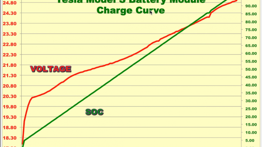
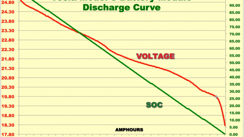
Note: The above calculations make a horribly wrong assumption… that the discharge voltage curve for LiPo batteries is linear. It is in fact, not linear, but I’m OK with this level of inaccuracy.
Turns out, I’m not OK with that level of inaccuracy. In a recent video by Jack Rickard, he provides graphs of actual charge and discharge curves for Tesla battery modules. Now, his were from an 85kWh pack, and mine is from a 60kWh pack, but the voltage levels of inflection should be practically the same. Given this new data, I’ve adjusted my set points.
LBCO: 19.7 Vdc
CV: 24.6 Vdc
| Model #: | Renogy RNG-100D |
|---|---|
| Max Power at STC (Pmax) | 100 W |
| Open-Circuit Voltage (Voc) | 22.5 V |
| Optimum Operating Voltage (Vmp) | 18.9 V |
| Optimum Operating Current (Imp) | 5.29 A |
| Short-Circuit Current (Isc) | 5.75 A |
| Temp Coefficient of Pmax | -0.44%/C |
| Temp Coefficient of Voc | -0.30%/C |
| Temp Coefficient of Isc | -0.04%/C |
| Max System Voltage | 600 VDC |
| Max Series Fuse Rating | 15 A |
| Fire Rating | Class C |
| Weight | 16.5 lbs |
| Dimensions | 47 x 21.3 x 1.4in |
| STC Irradiance | 1000 W/m^2, T=25C, AM=1.5 |
I had initially thought based on quick measurements, a drone photo of my roof and some room design software… that I would only be able to fit 15 solar panels on the roof of our Coach. Once I got those 15 panels in, I found I could add up to 19 total! Unfortunately, 19 is a prime number, so there wasn’t a good way to split them up into the same number of panels per string, so I had to drop one and go back to 18 panels total.
With 18 panels, that meant I could have 3 strings of 6 panels, or 6 strings of 3 panels. I had already purchased 8 awg wire for running power from the roof to the solar controller, so I did some math.
Knowing 8 awg wire has a resistance of 0.63 ohms per 1000 ft:
( 0.63 ohm / 1000 ft ) * 50 ft * 2 (round trip) = 0.063 ohms for 50 ft pair of 8 awg wire
Having this data as well as the panel specs lets us calculate the panels’ operating voltage and current, as well as the power loss for the wire run:
3s6p:
| Vmp: | 18.9 Vdc * 3 = 56.7 Vdc |
|---|---|
| Imp: | 5.29 Adc * 6 = 31.74 Adc |
| Vdc Loss: | 31.74 Adc * 0.063 Ohms = 2 Vdc |
| Watt Loss: | 2 Vdc * 31.74 Adc = 63.5 W |
6s3p:
| Vmp: | 18.9 Vdc * 6 = 113.4 Vdc |
|---|---|
| Imp: | 5.29 Adc * 3 = 15.87 Adc |
| Vdc Loss: | 15.87 Adc * 0.063 Ohms = 1.0 Vdc |
| Watt Loss: | 1 Vdc * 15.87 Adc = 15.9 W |
Conclusion:
Thus, I went with 6 panels in series per string to increase the voltage, but lower the current and thus, lower the power loss of the wire to the solar controller. Admittedly, the loss difference isn’t drastic, but every little bit helps!
| Description | Qty | Unit $ | Ext $ |
|---|---|---|---|
| Renogy RNG-100D 100w Solar Panels | 18 | 136.38 | 2454.90 |
| Tesla 4.5kWh LiPo Modules | 4 | 1161.50 | 4646.00 |
| Magnum MSH4024M Hybrid Inverter | 2 | 1758.13 | 3516.26 |
| Magnum PT-100 MPPT Solar Controller | 1 | 865.00 | 865.00 |
| AM Solar Tall Solar Panel Mount Kit | 18 | 82.29 | 1481.28 |
| Magnum ME-ARTR Router Controller | 1 | 289.99 | 289.99 |
| Magnum ME-ARC50 Advanced Remote Control | 1 | 181.03 | 181.03 |
| ECO-WORTHY ECO-PV6 Solar Combiner Panel | 1 | 169.99 | 169.99 |
| GE TL270SCUP Load Breaker Box | 1 | 22.24 | 22.24 |
| Blue Sea 3003500 600A HD Disconnect | 1 | 59.99 | 59.99 |
| Bogart Eng 1000ADC/100mv DC Shunt | 1 | 75.93 | 75.93 |
| Victron Energy Lynx Power In 1000ADC Power Rail | 2 | 141.10 | 282.20 |
| Victron Energy Orion 24/12-70 DC-DC Converter | 2 | 141.10 | 282.20 |
| Miscellaneous Wire, Connectors, Fuses and Holders | 1 | 1000.00 | 1000.00 |
| Approxmiate Total: | 15,300.00 | ||
Note: Prices above were what I paid and are likely to change. Further, the prices include tax and shipping where applicable.
There are a lot of intricacies to consider in this type of conversion. You should not take this project on just based off the details of this blog post. Instead, you or someone working with you, should have a deep understanding of electricity, electronics, LiPo batteries, Solar power, etc. I did loads of research and have a background in electricity and electronics. I poured over specification documents for so many pieces and parts, and still missed some fine print on one part that ended up costing me another $600 which I can’t easily recoup.
Here are the thoughts and decisions I made in no particular order.
- Should I convert all my coaches loads to 24v?
- Absolutely NOT! That would be a massive undertaking and is completely unecessary. I changed out my Inverter/Charger to be 24v compatible, then ran all the 12v loads another way.
- Ok, so.. I have a coach full of 12v loads, what did I do with them?
- These loads really boil down to two categories – High current loads and Low current loads.
- For High current loads ( Starting the generator, running the hydraulic pump ), I switched them over to operate off of the Chassis batteries. For my coach, these are two massive cranking batteries which easily power the two high current loads.
- For the Low current loads, I installed 2 x 70amp DC-to-DC converters. They run in parallel for a combined availability of 140amps @ 13.2vdc. This is plenty to run everything else in the coach.
- Uh… How do I maintain the charge state on my Chassis batteries now? Before, they would cross connect periodically to the House batteries to charge up!
- When we ordered our Coach, we had Tiffin install their ‘Solar’ package. This consisted of a single 145 watt 12v panel and low end charge controller. Since the new system is 24v, the existing panel was useless for our House batteries, so I switched it over to maintain the Chassis battery. That single panel is MORE than capable of maintaining the charge on the Chassis batteries!
Time for some Photos!


28 Comments
Robert Weiss · 2018-06-17 at 19:35
Oh, I see now 🙂
Statement: Your connectivity/connections may be the best I’ve seen.
Questions:
1) How do you charge 10kwh of storage with just 1.8kwh of solar?
2) Why 100w panels?
3) What has been your experience with these used Tesla modules. The idea of replacing my LA bank with this light weight and powerful solution really intrigues me, but I’m concerned about what I’d be buying for $1200~ per module.
Michael · 2018-06-18 at 11:31
Hey Robert,
Thanks for the interest! Here’s the answers inline to your questions:
1) How do you charge 10kwh of storage with just 1.8kwh of solar?
– We actually have 18 kWh of storage. We are normally plugged in at campgrounds. So, we use the Solar / battery more as grid offset than off-grid. If we get tight while off-grid, we also can fire up a 10kw generator to quickly recharge the pack ( in under 2 hrs, compared to 8+ hrs for the tiny FLA pack we had ).
2) Why 100w panels?
– They were the best for density on our roof due to existing obstacles. Higher output panels were considerably larger and didn’t allow for as efficient use of space ( like between the AC’s and the roof mounted awning for example ).
3) What has been your experience with these used Tesla modules. The idea of replacing my LA bank with this light weight and powerful solution really intrigues me, but I’m concerned about what I’d be buying for $1200~ per module.
– Oh man.. they work SOOO well. For a pretty good explanation of the capacity to cost to weight comparison.. check out this video: https://www.youtube.com/watch?v=pnCJFXWEVYs <- it's the most recent addition to my LiPo & Solar YouTube playlist.
Robert Weiss · 2018-06-18 at 17:27
I know it’s too late now but I spent a ton of time finding the 190 Toppoints I’m using. Same issue as yours – panels had to fit. The older 6×12’s were the way to go, although i am concerned about replacement. They’re just not made anymore. I weep everytime hail is predicted 🙁
The Tesla modules would resolve two of my issues: 1) current bank adds 1/2 ton to tongue weight 2) bigger bank is impossible given my space (duh, I already have 12 6v’ers). If i could resell my bank for acceptable buck, I’d take your approach in an instant. So mad that i missed it in my build research.
Robert Weiss · 2018-06-18 at 17:30
Also, I missed this the 1st time: “in under 2 hrs, compared to 8+ hrs for the tiny FLA pack we had”. The Tesla’s recharge fully 4x faster than FLA? Really?
Michael · 2018-06-18 at 19:53
Ya… FLA’s can only fast charge to 80% capacity, then nearly trickle from there to 100%. LiPo charge at full current ( 0.5C — 100 amps per module * 4 modules in parallel, 400 amps charge current capable without cooling needed ) up to about 95%. Since I only charge to around 90% anyway, I never throttle my charging. If I could generate 400 amps @ 24.7 vdc, I could top up in 2 hrs.. I can only get around 300 amps total w/ my solar and 2 x inverters, so I’d technically need a bit longer if going from empty to full. Bottom line though, FLAs take considerably longer to charge (if done properly) and have decreased cycle life if you don’t go to 100%. LiPo’s charge super fast and actually behave better if you don’t go to 100%… but don’t care where you stop below that.
Jason · 2018-09-07 at 19:01
Great setup Michael!! Very well planned out and written! I am currently building my setup and it is similar to yours. (Using Battleborn Batteries though). I have a question about the inverters. I am also installing two MSH4024M Inverters. It’s hard to tell in the pics but did you wire the neutral on the 110v side to be common between the inverters or are the neutral the circuits split up? I know the Victrons can do split phase but since I don’t plan to run 240v ever is this going to be a problem with the neutral common across the inverters? I already have the Magnums but would rather not have to split up my main breaker panel. Thanks! Jason
Michael · 2018-09-07 at 19:21
Hello Jason,
Unfortunately, I did have to split the neutrals on the inverter outputs. The problem is that without the ‘stacking’ feature that is available in the non-hybrid inverters, the output of these MSH4024M’s will not be in sync on when they switch from Shore to Inverted power. When this transition is not sync’d, the shore power breaker can trip due to ground fault. You can see the photos of my breaker box before / after the rewire at the bottom of the post.
Whichever inverter route you use, be sure to install EasyStart boxes on your AC’s if they draw power through the inverter. See my more recent post on this subject for more info.
Best of luck, and happy to answer any additional questions.
Michael
Jason · 2018-09-07 at 20:09
Interesting. I may have to rethink the wiring then. There is another rv video that set it up with the neutrals tied together. I don’t believe they are having any issuses as of yet but I’d like to know more. Take a look at the comments in this video (you can see my replies as well) https://youtu.be/oJGePg2vnCk
Michael · 2018-09-07 at 21:30
Hey Jason,
Thanks for posting this. I’ve replied to your thread on that video and hope to hear back from Justin. Here’s my understanding of the issue. When using 100% shore power, the neutral passes straight through, but when inverting, the neutral is disconnected from shore power neutral and instead is connected direct to mechanical ground. This causes the upstream breaker to see a power imbalance between hot and neutral legs since part of the current is returning over mechanical ground. This is the exact condition which causes a GFCI trip. I had to noodle on this for a good 10 minutes before coming to this conclusion… so I don’t think it is specific to hybrid function as I’d expect shore neutral to still be passed through the inverter instead of being switched over to mechanical ground.
Another interesting choice in that video — using two separate ME-RC or ME-ARC ( remote controls ), one per inverter. I’m using a single ME-ARTR to control the system with the only advertised shortcoming being that both inverters are always set to the same configuration ( which is fine by me ). I wanted the single point of control as I’m also using the Magnum Solar controller, Battery Monitor Kit and Auto-Gen start. I’m not sure how well this would work by splitting things across multiple remotes.
Michael
Michael · 2018-09-07 at 19:40
Jason,
One other thing of note. The Inverters, at least in my experience… will not both bulk charge at the same time. Thus, I can get charge current from the Solar and One inverter in parallel, but not both inverters. This limits my overall maximum to about 200amps of charge current. I’m more than OK with this, but Magnum has advised that they should ‘bulk’ in parallel ( the constant current phase of charging ).
I have had another interesting thing happen though, which I did not plan for or expect! Specifically, in some situations, I turn the ‘Charger’ shore power limit down to force use of the batteries ( time of use billing for our ‘home’ site ). What I did not expect, but saw happen… One inverter was providing ‘Load Support AAC (amps AC)’ to meet the coaches power demand on that leg, which was higher than my artificially configured limit. The other leg did not need all the power available under my artificial limit. So, that inverter went into bulk charge mode. The net result was that inverter 2 was taking excess shore power that it did not need, converting it to DC, then inverter 1 was taking that DC and inverting it back to AC to supply the other leg. Robbing Peter to pay Paul if you will. I was pleasantly, but thoroughly surprised! Supremely flexible power config.
Michael
Jason · 2018-09-08 at 09:03
Very interesting stuff. On the panel you have, can you initiate a ‘start bulk’ on your control panel? Once I switched to lithium (originally at 12v with factory MS2812 Inverter) I had to purchase the ME-ARC panel otherwise it would go straight to float because of the high resting voltages of the lithium. I think I am going to take the chance and install with the neutral shared like they did in the video. Mainly because my main breaker panel is all the way in the back and would require massive rewiring back there vs appx 5-7 feet of 6/2 cabling. I am (somewhat) trying to keep the RV in the state that it came to me (2018 Discovery LXE) should I decide to sell down the road. I am however going to remove the MS2812 that came with it and just place a small sub panel back there to keep those circuits happy. I can always rewire the 2nd leg and panel if I run into trouble with common neutral. I really wanted to keep using Magnum products and not switch to Victron. Hopefully it stays that way because I was very tempted! I also have a 2nd ME-ARC so I will let you know how the charging works once it’s set up. That was one of the main reasons I went Magnum, more watts and a lot more charging potential! 220A DC @ 24v. 5280 Watts would charge my 10KW Battleborn bank very quickly! That’s not even counting the 1600Watts of solar that I installed on my enclosed trailer.
Michael · 2018-09-08 at 16:52
Hey Jason,
Looking a the battleborn specs ( operating voltage 12.8v, bulk 14.4v ), two in series would bring the bulk voltage to 28.8v. Since the Magnum 24v units have a CV range from 24.0 to 32.0 volts ( in 0.2v increments ), you should easily be able to configure the inverters to charge to the proper end voltage such that even with the high resting voltage, the inverters should go directly into bulk mode ( as long as resting is < 28.8v for the series pair ). The two ARC's should be good for your setup and I'd expect it will allow both to charge in parallel. I may experiment with two remotes but I'm generally OK with how my setup is working now and don't mind the reduced total charge current. Magnum also made the ME-ARTR software upgradable ( via micro-sd card ), so that may provide a means of fixing the parallel bulk charge issue since I can see in the RS-485 traffic that the ARTR is sending different charge instructions to each inverter. (that reminds me, I should ping them about fixing this ). Eager to hear how your install goes, esp with the combined neutral. I think it's only an issue in RV parks with GFCI 50 Amp RV breakers (which I have yet to see one of), so it may be a while before you experience an issue. I may buy a 50 Amp GFCI for our 'home' lot here in Vegas just to test this situation more thoroughly. My current 120vac wiring from inverters to breaker panel is not ideal from a protection stand-point (I thought I had it covered, but realized a hole in my design when replying to your first post). So, I'd love to be able to use the 6/3 that's already pulled instead of my current "solution". Best of luck, and definitely keep me posted on your progress! Michael
Jason · 2018-09-11 at 12:50
Michael,
I wanted to let you know that I completed my installation over the weekend. It is working great! These Inverters are workhorses for sure! I can run all 3 ACs and they are barely heating up. Pulling around 130 amps @ 26v. One inverter handles 2 ACs and the other handles 1. My 12v setup would choke with only 2 running. Inverter overheated. The 12v cables would heat up, even with dual 4/0 cables and only 3 foot runs. The 24v configuration never even gets warm!
Charging is impressive. With the ARC-50 control panels, I can force both of them to go to Bulk and it will put 220A of charging power into the batteries. My victron BMK monitor hit 5500 Watts at one point! That should allow me to charge my 10KW lithium bank in a little over 2 hours! (if need be)
Everything is working as it should. Hybrid functions work like a charm. Depending on where I set the shore amps at, it does like you describe and 1 will charge while the other assists, depending on load on each inverter.
The only problem I have found so far is exactly as you described. If I use a dog bone adapter and plug into a 15A GFI outlet, it trips the GFI as soon as it transfers over to shore. The 50A RV plug in my garage works fine, but it’s not a GFI. Have you tried your setup on a GFI as of yet?
Overall I am very happy with the setup. I even rewired my slide controls and hydraulic jacks to run off the 3 Victron Orion 24-12 DC-DC converters. Now I can level and put out slides with the engine off as they see a nice steady 14v 🙂
Michael · 2018-09-12 at 20:26
Hey Jason,
Congrats on the install! I’ve not had a chance to test on a GFCI outlet w/ my setup as of yet. I’ll post an update when I run into one. Did you happen to install the EasyStart on your AC’s? If not, you should really look into it. You could hit issues like I did where the inverter trips on overcurrent for the Locked Rotor Amperage surge.
Michael
Jason · 2018-09-14 at 11:29
Michael,
I actually installed easystarts on my ac’s when I had the 12v system in place. They work wonders!
I was able to mitigate the GFI issue by disabling the neutral to ground relay in one of the inverters. I am not sure I am going to leave it this way. The other inverter will always complete the required neutral to ground connection when inverting however it makes me a little nervous. Also when on shore power the inverter disables neutral-ground anyway. I don’t see too many scenarios where it would be dangerous. I am still doing research on it. Other than that the system is working great! I just finished rewiring my levelers, slides and other components to the 3 victron orion 70amp DC-DC converters. Now I don’t have to run the engine to get the required 13.8v for the slides and jacks!
Jason · 2018-09-14 at 11:33
Also, any chance you could tell me where you got your solar panel brackets? My coach has the same style roof with the raised sides. I have been looking for something when I begin the solar install to have them sit higher so they are flush with the side rails. Any links by chance?? Thanks!!
Michael · 2018-09-14 at 12:32
Hey Jason,
The solar panel brackets are from AM Solar ( https://amsolar.com/rv-solar-panel-kit/mounting-accessories ), listed as the ‘L Foot – Tall 3 Hole’, they tap into the 35mm brackets from the same site. When you’re ready to order, be sure to call AM solar as they’re usually happy to discount once you’re past a certain quantity. As crazy as it sounds, the only thing holding my panels on the roof is 3M VHB tape! Just be sure to clean the roof well with alcohol and stick them in the right spot on the first try.. they won’t be easy to move! 🙂
eric yu · 2018-09-15 at 19:26
I did urge Samlex to update the docs. They are working hard to get it out.
Thx a bunch for your input for the current settings recommendation
While it appears to be “cool” hence safe, I will instead just put a four way manual switch for (off, A, B, A+B) to isolate banks from the Samlex. Samlex itself will safely disconnect base on monitoring its DC battery terminal.
When everything runs perfect, I can choose to leave it at A+B for default. In the meanwhile, I will start with A while using B for backup just like a boat dual battery configuration.
Safety aside, having a backup bank can be useful if a bank go down for any kind of unknown reason.
Obvious tradeoff is that in boondocks drain time, I need to switch over from A to B to keep the AC going.
Note I always have an embed generator in my configuration via the car alternator which acts as second AC source (via a separate inverter) to Samlex.
I wish I have the luxury as you. My RV (Mauck 2 Sprinter) has limited roof space. It can only fit 6 panels. I chose flexible (compromise for efficiency) for stealth reason. I only got 840 Watts of solar power. I do have limited AC drain due to small Frig. With latest battery/solar technology, AC luxury is not really viable for Boondocks time anyway.
eric Yu · 2018-09-12 at 07:48
Hi Michael,
Check out the Samlex All In One System.
http://www.samlexamerica.com/products/ProductDetail.aspx?pid=575
Love to hear your feedback how it can improve and/or simplify your system.
For my own personal convenience, I plan to use a simple AC inverter (running off my RV battery (alternator) as an embedded AC generator.
Tesla battery can then be charged from 3 separate sources in listed priority.
1. Shore Power
2. AC generator via (RV alternator => 12V RV battery => simple AC inverter)
3. Solar Power
I plan to use 2 banks of Tesla battery with a manual isolated switch (for safety upon thermal runaway since I don’t plan to hook up water cool feature of Tesla banks). One bank should be enough for most case with second bank for back up (boondocks)
I plan on using Tesla BMC (as is) for cell balancing. Samlex has to programmable safety settings to BEEP then eventually disconnect itself from the Tesla bank.
Thermistor (connected to Tesla thermal lead) need to be used to trigger thermal shutdown to the Samlex.
Michael · 2018-09-12 at 20:43
Hello Eric,
I would simply run both Tesla modules in parallel and forego the isolation switch. The modules can charge at 0.5C or discharge at 1C without cooling. I can’t even come close to this with my bank, so I doubt you’ll have a concern. 1C for my 4.5kwh modules is 200 amps. So, 0.5 is 100 amps. The higher capacity Tesla modules have a higher 1C rating. I’m tapped into the original Tesla BMS module w/ an Arduino Due using this code:
https://github.com/linuxkidd/TeslaBMS
It manages balancing and reporting of cell voltages as well as the Pos / Neg terminal temperatures. I’ve got a lot of geekery hooked into my system :). I plan to update the readme on that github with more specific instructions since it’s a bit unclear from the repo I forked and modified.
Regarding the Samlex — The spec sheet shows the charge voltage for their 24v units being 26-32vdc. Unless that’s wrong, or can be adjusted lower, it’s a complete non-starter for the Tesla modules. They can only be charged to a maximum of 25.2vdc. Even that level will drastically reduce the overall charge cycle life of the pack. Aside from that, the Samlex looks great, but not for Tesla packs I’m afraid.
I run my system with the inverters set to 24v and solar to 24.6vdc. This allows the hybrid Magnum inverters to go into ‘Load Support VDC’ — meaning, it pulls extra power from the DC side to supply the AC side of the inverter when the DC side goes over the configured charge level ( 24 volts ).
Hope this helps, and best of luck with your install!
Michael
eric yu · 2018-09-14 at 20:03
Hi Michael,
Samlex documentation is a little behind for the system with dual AC input.
Document is more up to date for the system with single AC input
http://www.samlexamerica.com/documents/manuals/11027-EVO-1212F-1224F-0418_Hrez.pdf
It is fully compatible with Lithium and it is fully programmable with the remote control
http://www.samlexamerica.com/products/ProductDetail.aspx?pid=607
It has the intelligence to monitor DC current coming from Solar controller input port and sum it with AC charger current to form a programmable max out current to the battery.
DC battery port will auto disconnect once hit programmable high voltage (charge mode) or programmable low voltage (inverter mode). I plan to use 24V for high and 20V for low.
I also plan to configure my Renogy 40 MPPT solar controller for 24V max output. My solar controller will be configured as 72V for six serial linked solar panel and 24V on its output.
What is the max current you set up in your system? I am thinking of 50A will be a good number to be used for Bulk Charging stage.
eric yu · 2018-09-26 at 17:29
Hi Michael,
Just to follow up with you progress with BMS modules.
1. I assume you are not using Tesla BMS modules as it would require a central BMS from third party to wake it up
2. If not, what are you using for BMS and what function will you depend upon it (outside of basic Cell Balancing function) for safety.
3. Can I assume safety is on two front…..Voltage abnormality (over/under)……Temperature overage (which typically relate to over voltage/current)?
Michael · 2018-09-15 at 11:42
Hello Eric,
Great to hear the Inverter has a broader range than the doc I saw. If you can, you may want to contact them and urge them to update the docs so that more people pick up their units!
The 1C rating of my modules is 200 Amps and the recommended charge rate is 0.5C ( 100 Amps ). I’m sure your modules are at least the same size as mine, so setting I would set the Bulk Charge Amps to the 0.5C limit for your pack. Remember that if you put two modules in parallel, voltage stays the same, but current doubles. Thus, 0.5C (100 Amps) * 2 modules in parallel == Recommended charge current of 200 Amps for the pack. Maintaining all cable lengths the same for your batteries will help ensure they charge as evenly as possible too. Limiting your charge current lower than the rated maximum (or the maximum of your inverter/charger, whichever is higher) would only slow your recharge rate which could be detrimental in situations where you need to bulk quickly and get off-grid again.
I have my pack’s max current set to 400 amps ( 0.5C * 4 packs ), but my charging capability tops out around 295 Amps ( 110 each from my inverters + ~75 amps max @ 24.2v for my solar install ). I have tuned my system so that excess solar power generated is used to feed the Coach’s AC power needs. This ‘grid offset’ usage help ensure I’m not letting ‘free energy’ go to waste and helps maximize my return on investment.
Eric yu · 2018-09-15 at 14:13
Thx for your insight on charging current.
Perhaps I will use a 4 way switch (A/B/A+B/off) for my battery banks.
I only have 6×140 or 840w of solar power. I anticipate my charging might come from car alternator while vehicle is on the move.
I don’t anticipate major DC drainage since I only have small frig. Nothing will satisfy boondock A/C anyway.
Michael · 2018-09-26 at 17:38
Hello Eric,
I am actually using the on-board Tesla BMS Boards ( Commonly called BMB ). I attach to it with an Arduino Due via a 3.3v to 5v bi-directional logic level shifter since the BMB is 5v and the Due is 3.3v. The Due and Teensy are the only two Arduino’s that can easily achieve the odd serial protocol speed of the Tesla BMB ( 612500 baud ). The Arduino code that I’m using is here: https://github.com/linuxkidd/TeslaBMS
At this point, I’m using it for monitoring and alerting as well as automatic cell balancing. I do intend to have over/under temp and over/under voltage protections, but I don’t feel those as a priority. The voltage levels are monitored and acted upon automatically by the Magnum inverters and solar charge controller. The temperatures will be regulated by a coolant loop (I have all the parts, but haven’t put this in place yet). So far, the modules are doing great after 6 months of use. Without enabling the balancing ability, the cells were all within 0.01 vdc of each other during steady-state after 5 months of use!
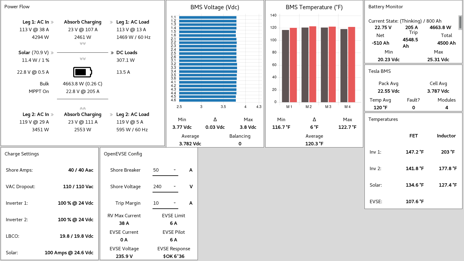
Here’s a screenshot of the full power monitoring interface that I have created for my RV:
eric Yu · 2018-09-26 at 18:05
I heard Tesla cells were cherry picked in the factory hence no need for balancing (practically). With that being said, cell can degrade with improper charging. Balancing and safety checking is a way to avoid the Oops that can cost $$$ if not tragic incidence. To me, priority is safety checking. As you stated, most inverter/solar controller already perform voltage checking for safety hence BMS/B checking will be redundant. Temperature is related to voltage/current that also seem to be redundant (outside of extreme cold that can be handled cheaply by other means. That leave balancing and stat collection. Balancing can be done very cheaply by various low cost cell balancer. Stat gathering (at 24v level) can be done via inverter utility software.
All and all, is there any value of leveraging the Tesla BMB?
Is there anything wrong by simply using “low cost” cell balancer such as Hobbyking Battery Medic?
Is there anything wrong by leveraging stat gathering and voltage over/under temp over/under safety auto disconnect?
Michael · 2018-09-26 at 20:38
Hello Eric,
It’s perfectly acceptable to use a low-cost cell balancer. I’ve seen some pictures of various BMS units (similar to the Battery Medic, if not it exactly) that show signs of melting plastic, presumably over the balancing resistors. From my perspective, since I have the skills and expertise to use the Tesla BMB’s, and they were purpose built, by Tesla, to handle these modules… it just makes sense for me to use them. It has the added benefit of giving me a data path for logging the data and long term trending. And no, there’s definitely nothing wrong with using a additional safety disconnect external of the inverters and charge controller. I’ll likely setup some additional protection, but in the interim, I have the system sending me email notices whenever a setting changes, and for over/under voltage, over/under temp. Thus, I have a bit of a backup in myself via the email notices.
eric yu · 2018-09-26 at 21:32
thx for your feedback
MOD: EasyStart 364 for AC – TurtleHerding · 2018-08-18 at 18:11
[…] our big electrical system upgrade ( MOD: TESLA Powered Tiffin! ), everything was working very well. […]
Comments are closed.