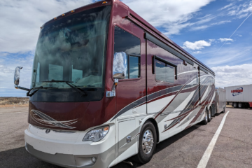
After our big electrical system upgrade ( MOD: TESLA Powered Tiffin! ), everything was working very well. Until…
Until, the outside temperature got up in the high 90’s while we were in far northern California. The first sign of trouble occurred on a Friday when I’d driven off to do some astro-shopping at a local star-party. Unfortunately, because of the rural nature of Tionesta, CA, I had no cellular signal and no notice of a problem until I got to the star-party. There, I was sharing internet with all the other star-party goers, so saying it was strained and slow would be an understatement. To make matters worse, the star-party location was a full hours drive away from the coach.
Once I got to the star-party, I got notices that all power was out in the coach. A vendor at the star-party let me use his Verizon phone (which some how had signal) to call my lovely wife. Unfortunately, I couldn’t get things figured out over the phone, so I raced back to the Coach in effort to return power and Air Conditioning as soon as possible.
It took a few days of troubleshooting and figuring to identify the ultimate cause. LRA. Oh, you’re not familiar with that acronym? I wasn’t either. It stands for ‘Locked Rotor Amperage’ and is a measure of how much current is required to start the Air Conditioning Compressor from a stopped ( locked ) state. It turns out, the 13.5k BTU Coleman Mach 8 Heat Pumps in our coach have an LRA rating of 63 amps! This value is specifically measured at 95 F outside temperature. When the temperature is cooler outside, the LRA is lower and likewise, if the outside temperature is hotter, the LRA is also higher.
In more research on this, I found that the brief high current inrush during compressor startup is short enough that a typical 50 amp RV breaker doesn’t react. Even the 20 amp breaker inside the coach for the Air Conditioner isn’t tripped by this massive current inrush, again, because it’s simply so short in duration. However, it turns out the Magnum inverters are MUCH more sensitive to this type of current rush. And with my new electrical wiring, all shore power flows through my 2 x 4000 Watt inverters. While the outside temperature had been cooler up until this specific Friday, we hadn’t hit an issue. But the temperature climbed and suddenly, we were getting daily trips on ‘over-current’ from the inverters.
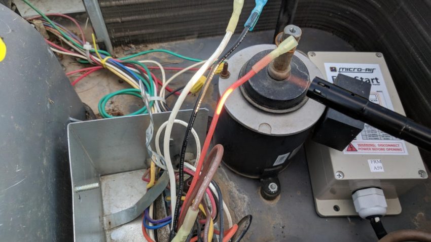
Luckily, MicroAir EasyStart 364 ships VERY quickly! By the end of the next week, I had 3 of them in my (often hot) little hands! Installation on the Heat Pump version of the Mach 8 was easy and MicroAir had a wiring diagram to help out. It wasn’t 100% clear however, so here’s the step by step for my non-plus Mach 8.

- Turn the breaker off for the AC
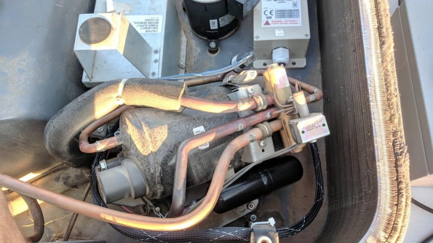
- Remove the 4 screws securing the AC cover
- Remove the 1 screw holding the fan impeller to the fan motor
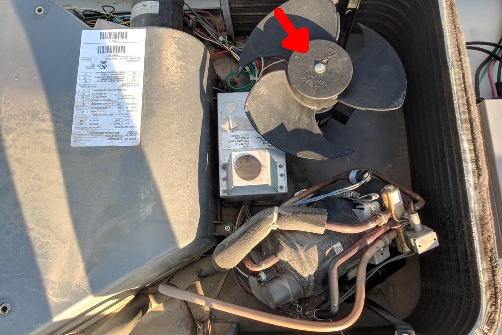
- Remove the 1 nut holding the outside electrical box cover on and remove the box cover
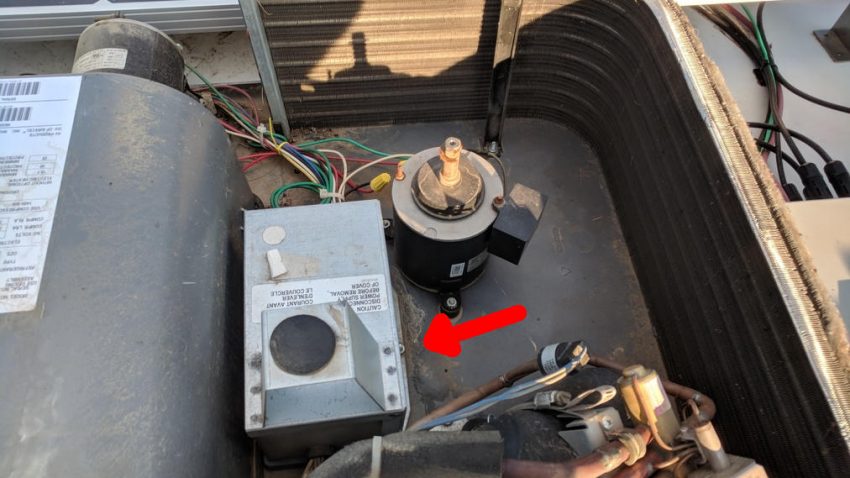
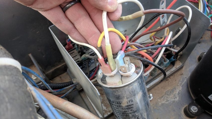
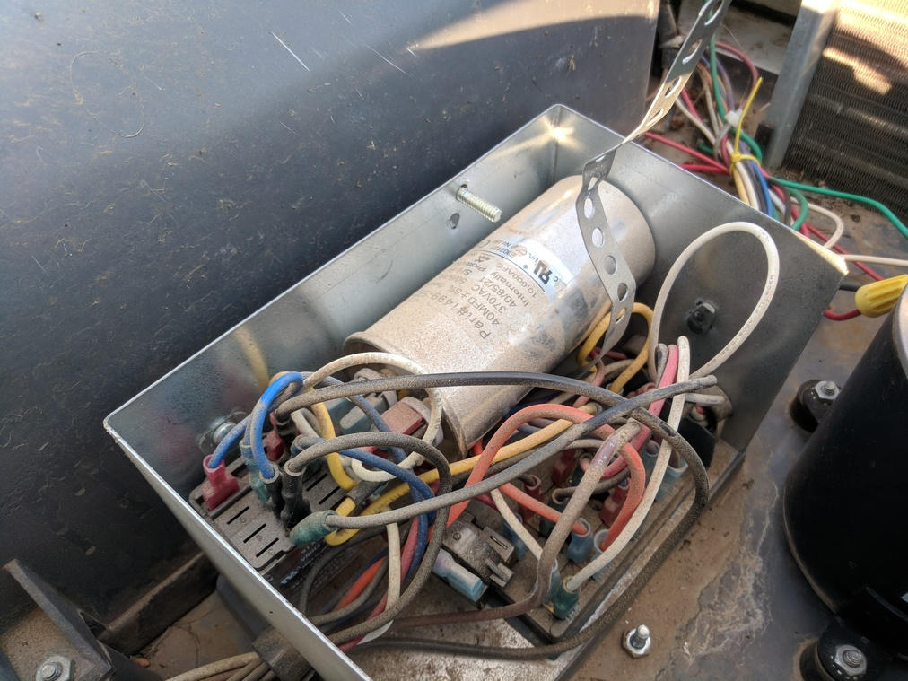
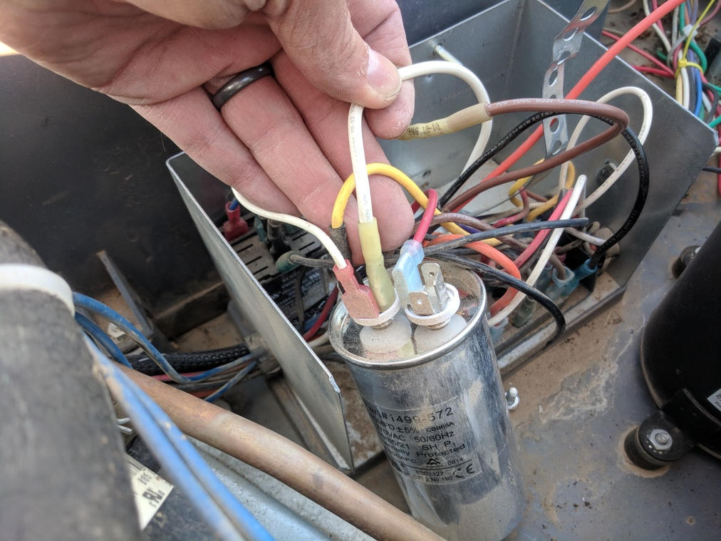
- Remove the 1 nut holding the strap across the start-up capacitors
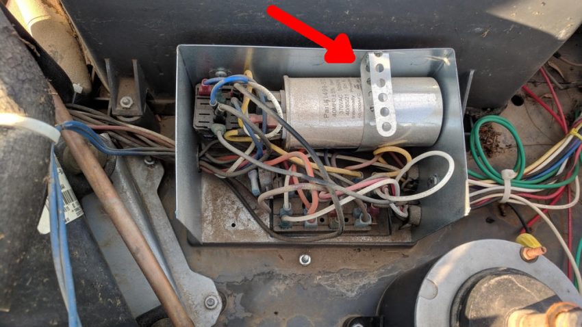
- Extend both capacitors up and out of their location
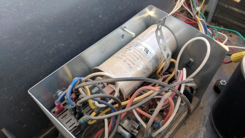
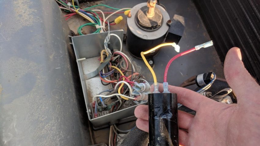
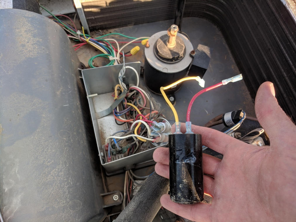
- Disconnect Red and Yellow wires that connect the smaller of the two capacitors ( Compressor Start Capacitor ) and put this in your spare parts box
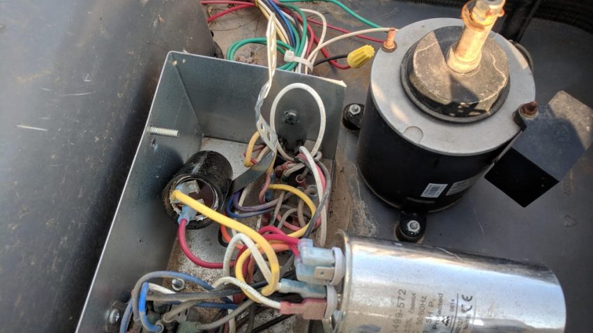
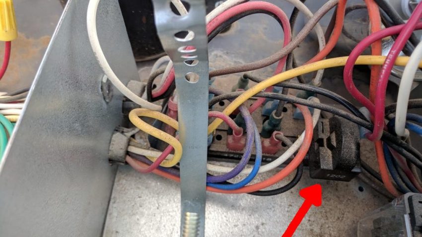
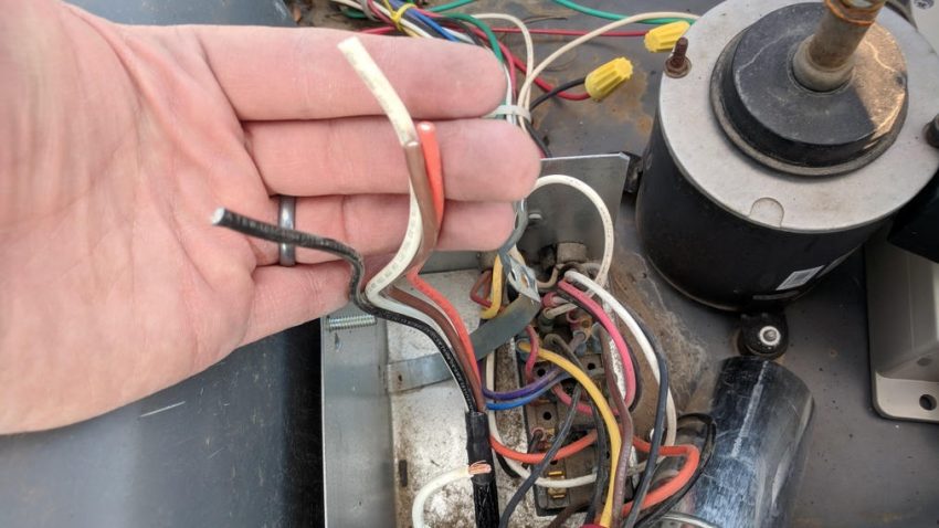
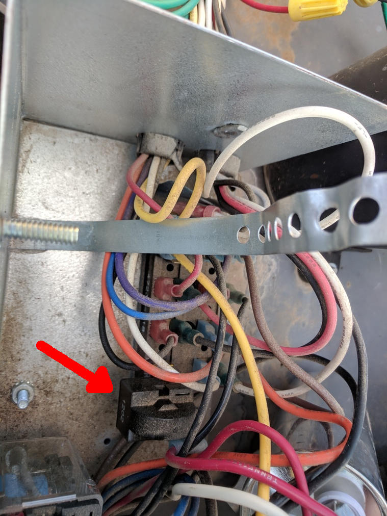
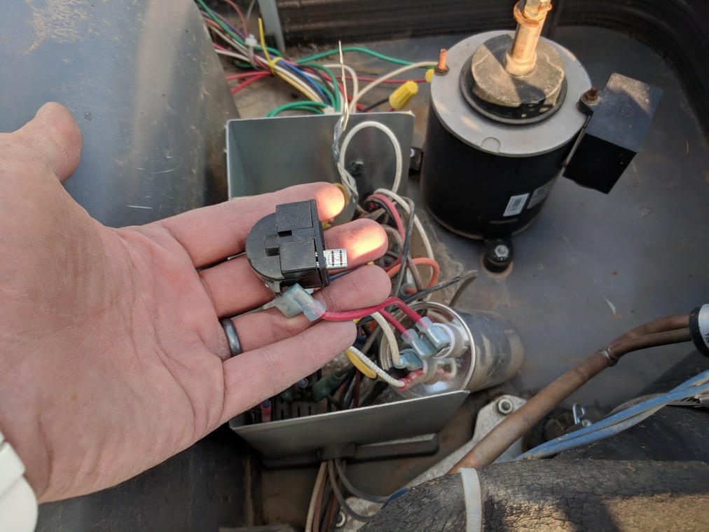
- Locate and remove the PTC
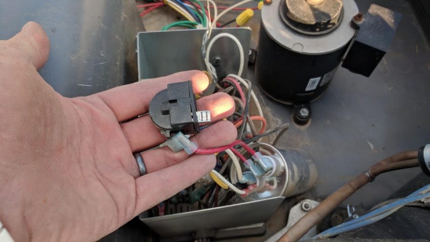
- Remove the Red wire from the larger cap which had connected to the PTC
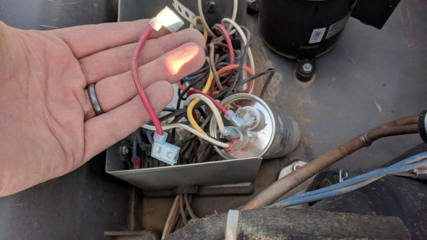
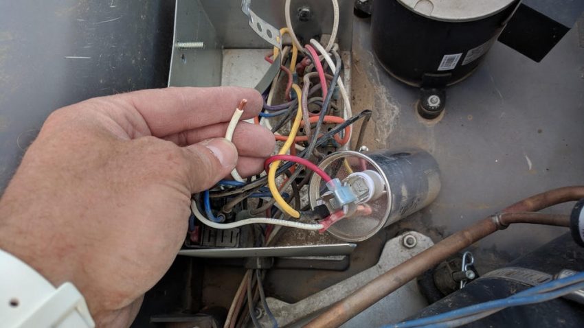
- Disconnect the White Compressor wire from the large capacitor ( it’ll be the thicker of the white wires )
- Cut off the push-on connector from the White wire and strip the wire back about 3/16″
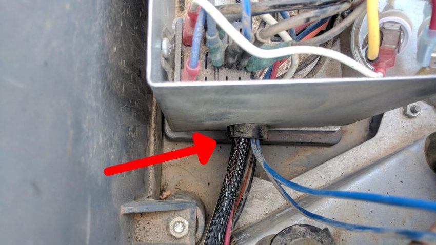
- Feed the EasyStart wire into the existing grommet on the side of the electrical box
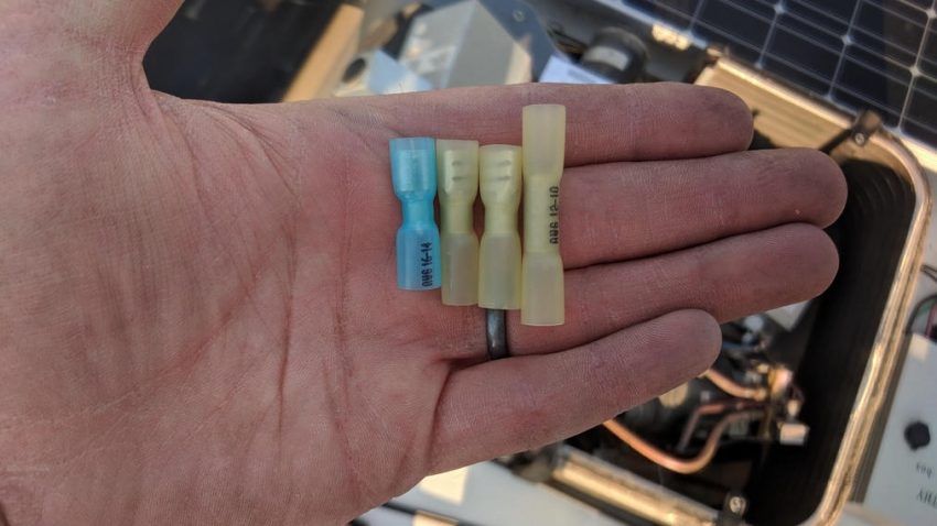
- Strip and Crimp connectors onto the EasyStart wires as follows:
- Butt Connector on Brown
- Push-on Connectors on White, Black and Orange wires
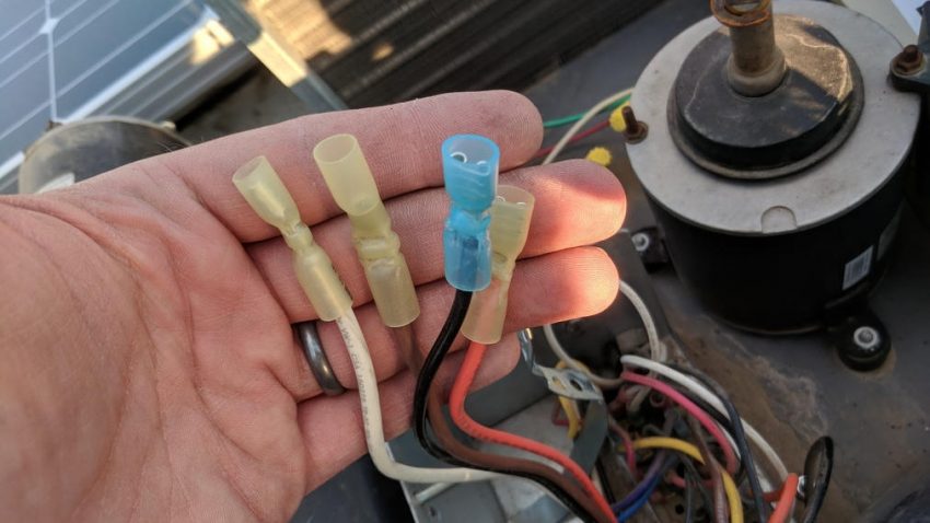
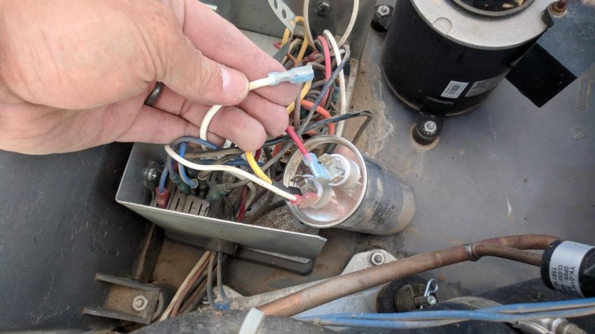
- Butt-crimp EasyStart Brown wire to White Compressor Wire
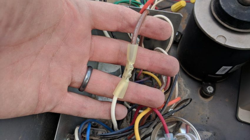
- If using heat-shrink insulated crimp-connectors, shrink all the connectors now
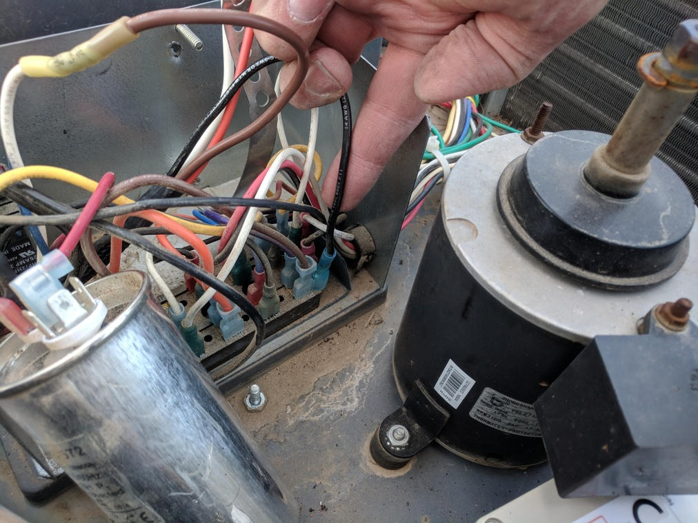
- Connect EasyStart Black wire to terminal block
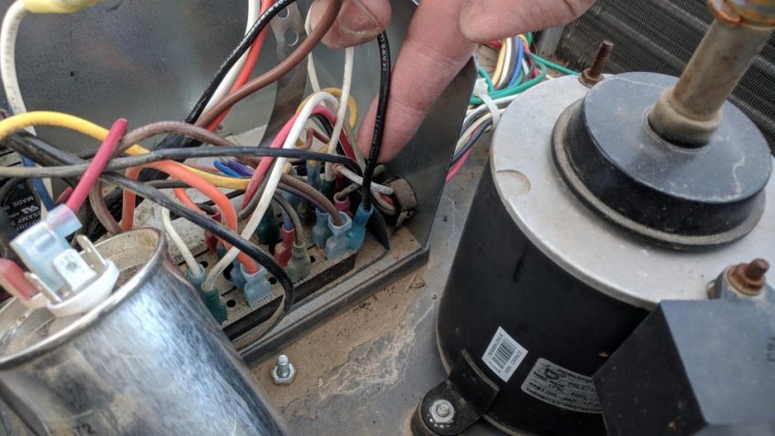
- Connect EasyStart White wire to large Capacitor terminal with White and Yellow wires
- Connect EasyStart Orange wire to large Capacitor terminal with Red wire
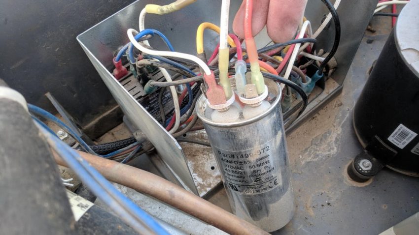
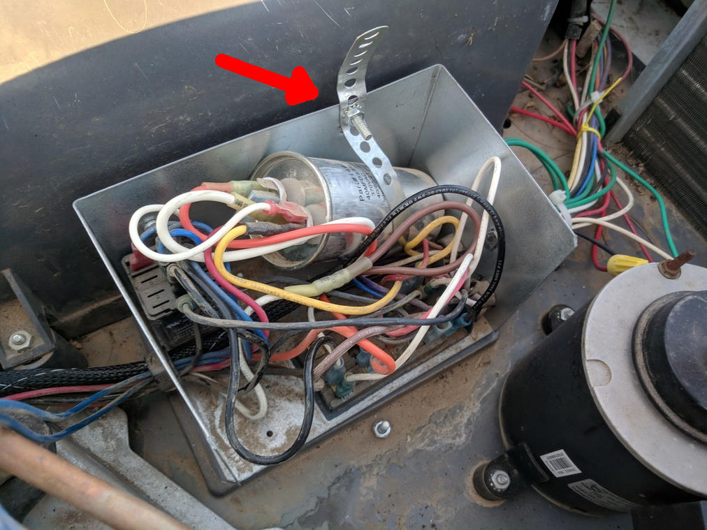
- Secure large Capacitor back into the strap and install the nut holding the strap
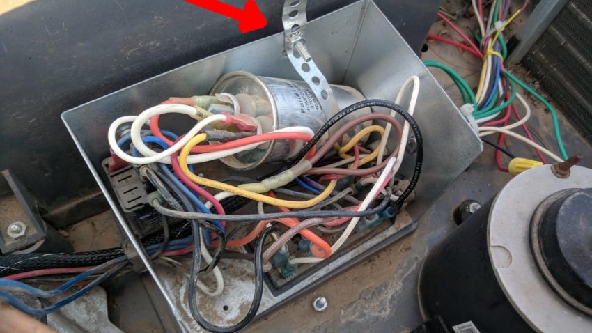
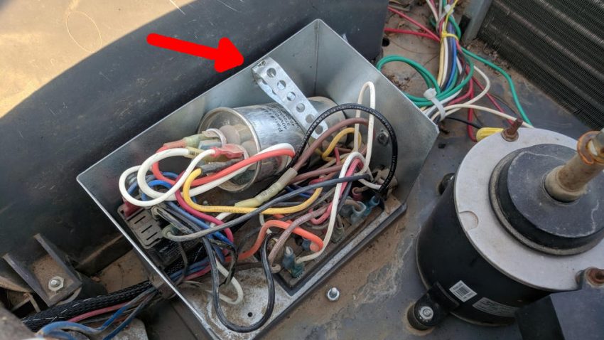
- Fold the strap over so the lid will fit back on the electrical box, be careful not to contact any of the wiring with the strap (this will prevent future shorts from the strap vibrating against the wires
- Re-install the electrical box lid and its nut to hold it in place
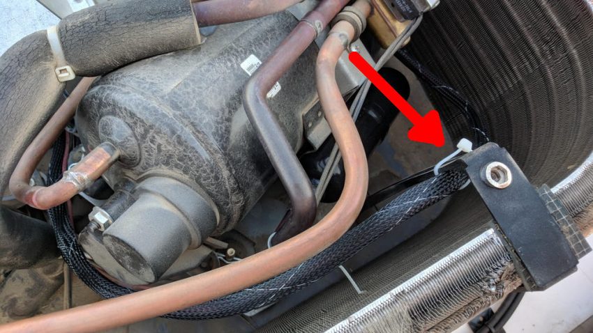
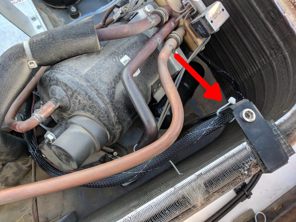
- Zip-tie the EasyStart wire bundle to the coil support bracket
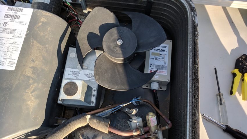
- Clean the floor of the AC between the external fan motor and coil, then secure the EasyStart box with 3M VHB tape to the floor of the AC unit
- Re-install the external fan impeller and secure it with the screw removed earlier
- Re-energize the AC Compressor breaker
- Test the AC Unit to ensure it starts and the compressor turns on after a 5 second delay once cooling is called for


NOTES:
- The EasyStart will be in learning mode for the first 5 starts.
- After that, it will use its learned starting profile to minimize the AC compressor start current.
- You should also observe that the AC is quieter overall by a noticeable amount!
- The EasyStart is 100% compatible with the Mach 8 Hush Kit since they interface with different parts of the AC unit. (Yes, I have both installed on all 3 units).
Now, I don’t have to worry about my Inverters tripping on Over Current during my AC start-ups!